With its four L SUB 1500 A bass bins, the LINEAR 3 High Performance Pack delivers powerfully coupled low end to your audience, particularly when they’re set up as a broadside line array with spaces between the bins. Read on to learn more about this basic type of array.
Very broadly speaking, ordinary bass reflex bins have an omnidirectional pattern of throw, with cardioid setups being the exception to the rule. It’s complicated, but suffice it to say that bass bins are somewhat lacking in the directivity department because lower frequencies have longer, more diffractive wavelengths. That’s not bad per say: For example, one standalone sub distributes sound uniformly in all directions. The pattern is not a perfect circle, but close enough for our ears as shown in fig.1. This explains why HK Audio LUCAS systems deliver such satisfying results with just one mono sub bin. The same applies to a mono cluster where several bass bins of the same type sit right next to each other in front of the stage.
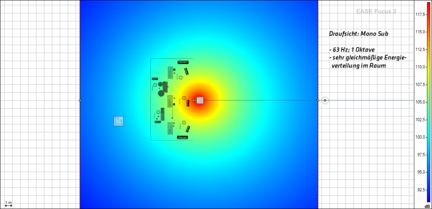
Figure 1: A mono sub’s energy distribution – Top view of a mono sub, distributes energy very uniformly, 63 Hz, 1 octave
A very common alternative is to stack the subs to the left and right of the stage. This is the classic go-to configuration. We like it use it for reasons of space, simplicity, or just because the speakers’ manufacturer built his speakers to work well that way. Often these stacks provide the perfect base for top units, and they do get the job done for most gigs. However, you can get more and better sound out of a system. These stacks are fine for top units because the spacing between the left and right speakers is such that they cover the audience area well and create a good stereo image. The subs, however, are usually too far apart. This overly generous spacing leaves gaps in the low-frequency throw-pattern and creates islands of concentrated sonic energy. The areas surrounding these islands are plagued by cancellations as shown in fig.2.

Figure 2: L/R stacks’ energy distribution – Top view of an L/R stack: -63 Hz, 1 octave, creates spurious side-lobes, causes cancellations
The smart solution is to move the subs back in a little closer together in a setup variously called a sub array, a sub line or a broadside. Whatever you wish to call it, this configuration minimizes these undesirable islands of concentrated energy and cancellations. It also has a directional effect where the system projects bass frequencies more uniformly across the audience area as shown in fig. 3.
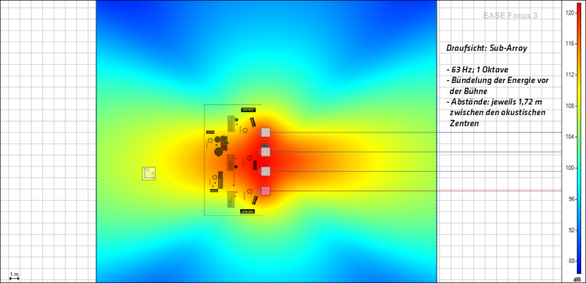
Figure 3: A sub array’s energy distribution at 63 Hz, 1 octave and 1.72 m spacing, top view of a sub array, 63 Hz, 1 octave, energy coupled in front of the stage, spacing: 1.72 m between acoustical centers.
If you want to achieve a coherent and directed wavefront, then two loudspeakers’ acoustical centers may be no further apart than half the wavelength (λ/2) of the highest frequency to be coupled. Cancellations occur at frequencies higher than this as shown in fig. 4 and 5.
So what does this mean to us when we go to line up subs? For the sake of discussion, let’s say we want to set up four L SUB 1500 to couple their signals and provide relatively uniform coverage across the target area – in this case, the audience zone in front of the stage.
Let’s also assume that we’re using a 100-Hz crossover filter for the L Sub 1500. This means the highest frequency to be coupled is 100 Hz. The wavelength at 100 Hz is around. 3.44 m, calculated using the following formula: c (speed of sound) = λ (wavelength) * f (frequency). According to this formula, λ/2 of 100 Hz comes to 1.72 m. In other words, the acoustical centers of two L Sub 1500 may not be more than 1.72 m apart. The subs are around. 0.5 m wide, so the distance between the side panels of one sub to the next should be no greater than 1.22 m.
Figure 4 shows the performance of an array with subs placed at equal distances at 125 Hz, which of course is a frequency higher than our designated coupling frequency of 100 Hz. Even at a frequency just 25 Hz higher, you can already see some slight cancellation at the edges of the target area.

Figure 4: A sub array’s energy distribution at 125 Hz, 1 octave and 1.72 m spacing
Figure 5 shows the energy distribution at 125 Hz with the spacing distance increased to 2.22 m. You can see more islands forming and more cancelations occurring in the target area.
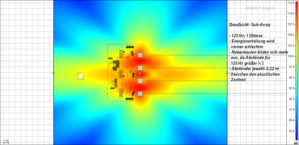
Figure 5: Top view of a sub array, 125 Hz, 1 octave, energy distribution increasingly deteriorates, sidelobes begin to form as the spacing for 124 Hz is greater than λ/2, spacing: 2.22 m between acoustical centers.
Practical tip: A simple sub array does a good job of coupling the subs’ energy and directing it towards the FOH desk and audience area. This is beneficial for most events in halls where the audience in front of the stage is there to enjoy the show and the sides of the hall are lined with catering counters and bars staffed with people who would rather not get blasted by the FOH sound. The wider the array and the more bass bins you deploy, the more directed the line’s signal. You should also bear in mind that the thrust of a simple sub array’s signal is directed not only towards the FOH, but also towards the stage as shown in figure 3.